AST Configuration >
The
Aircraft >
home

|
|
|
|
|
|
 |
AST Configuration click on the links below for more of the
manual...
|
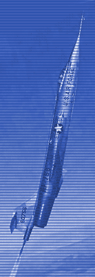
Introduction & ConfigurationThe website is dedicated to the AeroSpace Trainer and its design mission, as it was intended to perform for training of test pilots under the conditions that prevail outside the aerodynamic region of flight. In consideration of austerity, the configuration of the AST was that of a standard F-104A Lockheed Starfighter, with a great many modifications for the unique space flight. Unfortunately, all the published information, including this AST Partial Flight Manual (PFM) specifically excluded maximum zoom information and all data outside the very restricted limits, as directed by the Yeager Accident Board. It reflected only the results of the tests flown by test pilot Robert Smith after those limitations were established. It also reflects changes in the aircraft that were directed, and not used for any maximum zooms. For the purpose of understanding the intended use of the AST, maximum zoom mission, much of the performance data of PFM are inadequate and other changes are necessary to PFM to relate the max zoom missions. Systems Summary: (Refer Partial Flight Manual pgs. 1-8 thru 1-27) The AST Center of Gravity was at minus five percent (-5%) of the Mean Aerodynamic Chord (MAC), when fully serviced for zoom takeoff and would move aft to between 24 to 26 on maximum zooms, as jet fuel and H2O2 oxidizer were depleting. The designers eliminated a problem during the critical space period by canting the line of attachment (nose down) on the rocket motor installation, so that as the fuel and oxidizers were used and the center of gravity moved, the rocket was thrusting through the c.g. at burn-out of the rocket motor, thus no sudden pitch change would result. Pitch effects at light up were unnoticeable doing 2.2 Mach at 35,000 feet, so the design trade off was a wise safety consideration. Cockpit Summary: (Refer: Partial Flight Manual pgs. 1-1 thru 1-7) The attitude indicator was an All Attitude Reference System, AARS, derived by one significant change to a Navy instrument, similar to Air Force standard. Due to Navy use of instrument landing system (ILS) for carrier approaches in weather, they superimposed ILS needles on the attitude indicator to provide a single instrument for attitude and direction. The standard AARS provided roll, pitch and heading indications from its 360 degree gyroscopic ball and had two perpendicular needles superimposed to provide ILS commands for heading (vertical) and glide path (horizontal). To modify the AARS to their purpose Lockheed designers merely connected the vertical needle to a large vertical wind vane on the extended nose-boom (pitot tube) and the horizontal needle to a horizontally oriented vane. With this nifty mod they replaced ILS with yaw and angle of attack in lieu of glide path and slope, respectively. That one gage, off the shelf, provided all four references required for zoom attitude: The Pitch and Roll indicators and the Angle of Attack and Yaw commands. The angle of attack command represented by the horizontal needle was controlled by a switch, which allowed a pilot to select one of 3 null alphas for guidance position on various profiles, thus allowing the pilot to correct toward the needle, until centered, like ILS approaches. Likewise the zero yaw position was directed by position of the vertical needle at center. |
| next section |