AST Configuration >
The
Aircraft >
home
|
|
|
|
|
|
 |
AST Configuration click on the links below for more of the
manual...
|
|||||||||||||
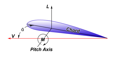
Aerodynamics of the ASTDuring the aerial portion of max zoom the AST performed as an airplane with lift and drag resulting from airflow over and around it. Both are the result of air impacting surfaces which either change the crafts position, lift, or slow it, drag. Both are the result of dynamic pressure (q), which is equal to ½ air density times the velocity of the aircraft squared. Thus q is proportional to altitude and to the square of the velocity, thus doubling speed quadruples q, etc. Therefore, to achieve virtually no lift or drag, necessary to achieve space simulations, required a very low, nearly zero, q obtained by very slow speed at very high altitude. The two forces felt by an airplane, lift and drag, are merely functions of q multiplied by the surface area affected. A typical resulting force (drag) is what you feel when you hold a flat object against the wind in a speeding car. Thus the force is four times greater if the speed is doubled and will be lower at the top of a mountain than at sea level for the same speed. Aerial Flight Airplane flight is the result of air moving over the lifting surfaces, and the air moves faster over a curved side, creating a lower pressure (Bernoulli Principle) than on the other side. Thus aerodynamic lift pushes toward the more curved side. That is true for every lifting surface, wings, ailerons, stabilizers (i.e. vertical and horizontal) and rudders, propellers, even the turbine blades of the jet engine. It is impossible to get aero lift without induced drag created by the friction of the air contacting every surface and added drag resulting from the energy transferred into the air as a result of disturbances of the air, called non-linear or turbulent flow. Linear flow, where the air flows in parallel streamlines, creates far less drag, so the shape and texture of the surfaces are important, as well as the angle at which the air approaches it, called angle of attack (alpha).
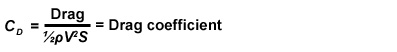
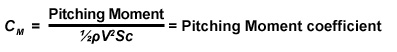
The amount of lift created by an airfoil or lifting surface depends on the angle at which it impacts the air, alpha. Actually, the airplane can be considered stationary and the wind passing by it, as in a wind tunnel, and all engineering calculations are the same, whichever the case. Whenever an airfoil is at an alpha that creates lift, positive or negative, then a component of total drag, called induced, is the result of velocity, air density and the effective surface area of the airfoil, just as lift is. Equations used to express relationships are based on coefficients of lift or of drag, found simply by testing every new shape in a wind tunnel over the range of useful angles of attack and airspeeds. As in this case, much of design is empirical and it is interesting to note that the Wright Brothers’ construction of a crude wind tunnel was a factor in their success. The mathematical relationships then allow analysis and design with equations based on the coefficients for different configurations/designs:
The enumerable sets of equations required for analysis and design of modern airplanes are extremely complex and made practical only because of the advanced state of computers. Modern airplanes are sometimes designed with unstable features to gain performance advantages, and made flyable by computerized control systems operating between the pilot and the control surfaces, since human response is quite limited. It’s interesting and argumentative, though a bit discomforting for pilots that these advances plus many others that already allow unmanned military drones to perform attack missions, will toll an end of pilots in the cockpit, much sooner than we might expect. Keep in mind that, even with technology of the 1970’s the computer, not the pilot could best handle the difficult and critical reentry and descent on Space Shuttle, and that capability was never a factor in either Challenger or Columbia accidents. Oh, by the way, commercial airline automated flying is the easiest of all to implement with many more layers of safety backups than currently available with human control. Airplane Performance: In addition to Lift, the other inherent parameters of powered flight are: Thrust, the force to propel the airplane with propeller, jet or rocket: Weight of the entire airplane, which of course acts vertically through its center of gravity and: Profile drag, which is the resultant drag, exclusive of lifting surfaces, due to the shape of the vehicle and impact angle of the air. With thrust acting through the c.g., trim is the stable condition at which the airplane is content to do what it is doing and will continue, if undisturbed. The pilot has trim controls for the three axes so it can be established and no control forces are required to remain in trimmed flight. Without disturbances, hands-off flight results, with a stable aircraft design.
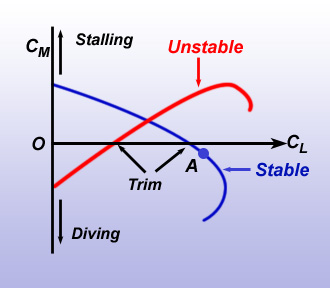
Airplane Stability All of these discussions assume a rigid airplane, which is never exact. Basically, this assumption allows only the flight control movements to affect the aircraft. Especially, in high speed flight the flexibility of the vehicle can have dramatic and unexpected results, catastrophic in the case of individual airfoils, for example, some of which are even beyond mathematical predictions and require very cautious and gradual flight test into the stability envelope. Static stability addresses the response of the vehicle to small disturbances when it starts in equilibrium (trim) and how it responds immediately after the disturbance; merely whether it is stable (moves back toward its trim) or unstable (moves away from trim), not what it does thereafter. Though, seemingly trivial, an airplane that is statically unstable would be pretty awful to fly no matter its dynamics, because it could never be trimmed so the pilot would work constantly to control even level flight. The three axes can be considered independently for static stability with reasonable accuracy. For example, in the longitudinal case, the airplane remains in symmetry to the other two planes. As with lift, the torque forces required to rotate an airplane about its three axes are determined for different configurations in a wind tunnel and like the Coefficient of Lift are recorded as Coefficients of Moment, different for each axis. This allows determination of what occurs to an airplane when it speeds up or slows down from the trim or when the stabilizer is moved up or down to pitch the airplane. Similarly for roll and yaw. A stable system is when a gust pitches the nose up and the moments rotate it back down to trim condition. In such a case the CM is opposite the change in CL. Thus the equation; Static Longitudinal Stability = - dCM/dCL Conversely, a positive rate of change of moment coefficient with respect to rate of change of lift coefficient would be unstable. Static Longitudinal Instability= + dCM/dCL
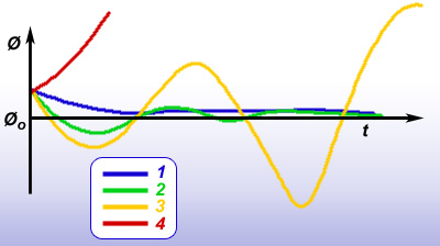
The yaw and roll planes, are orthogonal to the longitudinal plane, but gusts can provide disturbance in any plane. Both of these are usually statically stable under anything but grossly abnormal aft of center of gravity, which would be outside the safe zone to fly the pitch axis, in any case. Yaw stability is the result of the long lever arm from c.g. to vertical tail and roll is generally provided by dihedral of the wings, where the tips are a bit higher than the roots, so if a wing drops a bit a little sideslip occurs and corrects it. Dynamic Stability Dynamic Stability addresses the entire process of response (long term effects) of an airplane to any disturbance. The equations for dynamic motions are very complex, far from the simple problems of static stability. Dynamics can also cross over within the 3 axes, in which cases it involves a much higher degree of mathematical solutions, requiring simultaneous solution of three partial differential equations with calculus. Dynamic reactions of aircraft vary greatly but display four possible groupings, with unique characteristics for each, when combined with the static stability of the particular aircraft. 1. Simple Subsidence: statically stable, dynamically stable. 2. Damped Oscillation: statically stable, dynamically stable. 3. Divergent Oscillation: statically stable dynamically unstable. 4. Divergence: statically unstable, dynamically unstable.
Case 4 is absolutely ruled out for man-controlled airplane design, since there could be no trim point and that would be the source of constant attention to flying the airplane, far to demanding or even impossible for the aircrew, whereas the other three might be considered. Case 1 is ideal from the standpoint of requiring the least possible attention from the pilot, but with some significant drawbacks. No matter what disturbs the aircraft it hurriedly returns to trim without oscillations. However there are inherent disadvantages to having extreme stability, especially in performance tradeoffs, because drag, for example can be greater decreasing many performance features. Reduced responsiveness of the controls can be another shortcoming. Cases 2 and 3 must be evaluated against two additional and primary parameters of dynamic stability. Both of these affect the ability for human control of dynamic responses. First is the period of the motion created by a time-constant; that is the frequency with which the airplane passes back through its original position. The other is damping factor; the rate at which the oscillations increase or decrease, which is the slope of a curve drawn so as to touch the maximum excursions of the respective curves in Fig. 4. The steeper the curve, the less the system attempts to remain controlled and the more correction required by the pilot to avoid exceeding limits, like stall or to fly precisely in weather or close formation. Clearly, if the period is long (large time constant) the ability of a pilot to cope with instability is improved significantly, making it less uncomfortable and disturbing. Likewise strong damping is preferable and can make such a system preferable. In the real world of aircraft design, nothing comes free and everything is a trade off, even in stability, where a very stable airplane can be a very poor fighter because it reduces responsiveness of the vehicle, and other performance drawbacks. One of my most unique experiences in flight test was flying a specially equipped Mc Donnell Douglas F-101A, single seat, twin engine Voodoo, fighter, in 1963. It was equipped with a side arm controller, the first of its kind, now standard in our F-16 fighter. A special flight control system could be turned on to override normal flight controls and had the unique capability to allow the pilot to select the basic type of stability, as above, and to vary these two primary stability parameters changing the airplane from very stable to absolutely uncontrollable. All the factors could thereby be mixed or matched for a very broad look at stability. The F-101, like the 104 had a high horizontal stabilizer and thus aerodynamic pitch-up risks, so it was equipped with a “kill” paddle on the stick for immediate disconnect of the flight control system whenever the reaction was headed outside safe limits, which the test pilots had to use on many occasions, and pronto! The pilot’s reaction time had a lot to do with the allowable limits, so we could contest on how far around a turn we could fly it before having to abort, but no one can deal with really bad instability, no matter the skill level. Lateral, and yaw axis stability are basically the same in principle, but quite different in results, but those axes can be involved in serious stability problems, also. A couple of very critical dynamics cases are worthy of mention. One is that of control surface (rudder, ailerons, etc) flutter, which occurs suddenly at high speed when the airflow becomes disturbed and the frequency of that disturbed air matches the critical frequency response of the surface at its connections to the aircraft, or structural joints. The result can be a sudden disastrous failure of the airplane’s structure or loss of a critical control surface. The other is known as inertial, or sometimes called roll-coupling. That phenomenon is the result of the moments of inertia about the roll axis of the airplane. It occurs as speed and roll rate increase, also resulting in catastrophic sudden structural failure of the empennage (tail) from a sudden extreme yaw induced by a high roll rate. Both have occurred in test flights, notably before the advent of fast computers when the known equations were too complex for automated analysis. Incremental testing into increased risk, with data evaluation between flights was the only test option, which was slow and very costly, as a result. But there were a few unstable aircraft that proved useful. I flew only one such aircraft that had the problem in the roll axis, the H-21, helicopter. Stick free, it would have rolled on its back in short order, which was irrecoverable, and all it took to demonstrate that was to let go and tap the stick in roll. But the period was long enough to recover with the controls, but without hesitation. It meant you never let go of the controls on the H-21, flying it constantly, so you really didn’t even notice the instability. |
 Flight performance is affected by the two
major parameters, lift and drag, which are
summed at the aircraft level, where they always
act through the center of gravity (c.g.) where
the entire weight of the aircraft is in
mass-balance about all three axes. The
designer’s task is synergy between mass balance
and force balance.
Flight performance is affected by the two
major parameters, lift and drag, which are
summed at the aircraft level, where they always
act through the center of gravity (c.g.) where
the entire weight of the aircraft is in
mass-balance about all three axes. The
designer’s task is synergy between mass balance
and force balance. 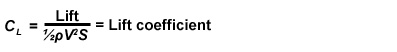
.jpg)
| previous section | next section |